Close Menu
FreeHubFreeHub
  • Home
  • English
  • Maths
  • Difference Between
  • NCERT BOOK
Facebook X (Twitter) Instagram
  • Home
  • English
  • Maths
  • Difference Between
  • NCERT BOOK
Facebook X (Twitter) Instagram Pinterest Vimeo
FreeHubFreeHub
  • Home
  • English
  • Maths
  • Difference Between
  • NCERT BOOK
subscribe
FreeHubFreeHub
Home»NEET Question Answers»Diagram of an AC Generator and Description (NEET Physics)
NEET Question Answers

Diagram of an AC Generator and Description (NEET Physics)

BagavanBy BagavanNovember 1, 2024Updated:November 18, 2024No Comments2 Mins Read
Share Facebook Twitter Pinterest LinkedIn Tumblr Reddit Telegram Email
Share
Facebook Twitter LinkedIn Pinterest Email

Draw a diagram of an AC generator and describe it. Derive an expression for instantaneous value of induced emf.

Hint: An A.C. This generator is an electronic apparatus designed to transform mechanical energy into electrical energy through the principle of electromagnetic induction. Create a diagram by conducting a schematic analysis of its operation, ensuring to include all key components. The formula for induced electromotive force (emf) can be derived using the equation for magnetic flux in the coil and Faraday’s law of induction.

Formula Used:

Magnetic flux across the coil, [latex]ϕ=NBAcosθ[/latex]

Faraday’s flux rule, [latex]ε=−\frac{dϕ}{dt}[/latex]

Complete step-by-step answer:

A generator, or dynamo, is a device that transforms mechanical energy into electrical energy. The term “generator” is somewhat misleading, as it doesn’t actually create energy; instead, it merely changes energy from one form to another.

An A.C. A generator is a device that generates an alternating current, meaning it reverses its direction at regular intervals. This device transforms mechanical energy into a fluctuating type of electrical energy. The operation of AC generators is based on the principle of electromagnetic induction. When a closed coil is spun in a uniform magnetic field with its axis perpendicular to the field, the magnetic flux associated with the coil changes, inducing an electromotive force (emf) and, consequently, a current within it.

The different parts of an A.C. generator include:

  1. Field magnet
  2. Armature

iii. Slip rings

  1. Brushes
  2. Source of energy

The following diagram shows an A.C. generator:
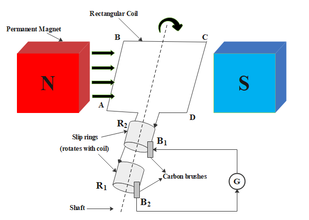
seo images


The expression for instantaneous value of induced emf:

Consider the number of turns in the coil of the A.C. generator are N, its face area for each turn is A, the magnitude of the magnetic field is B and θ is the angle which normal to the coil makes with magnetic field B at any instant t. Let the angular velocity with which the coil rotates be ω.

At any moment  t , the magnetic flux associated with the coil of the A.C. generator can be expressed as:

[latex]ϕ=NBAcosθ[/latex]  or, 

[latex]ϕ=NBAωt[/latex]

According to Faraday’s law of flux, the induced emf can be expressed as:

[latex]ε=−\frac{dϕ}{dt}[/latex]

⇒[latex]ε=−\frac{d}{dt}[/latex](NBAcosωt)

⇒[latex]ε=NBAωsinωt[/latex]

[latex]∴ε=ε_∘sinωt[/latex]

where[latex]ε_∘=NBAω[/latex]. This equation gives the expression for instantaneous value of induced emf.

Note: The generation of A.C. is more economical than the generation of D.C. Furthermore, the alternating voltage can be easily increased or decreased to meet the circuit’s requirements using a transformer.

ac generator ac generator and electric motor ac generator in hindi construction and working of a ac generator derive an expression for instantaneous emf in ac generator difference between ac generator and electric motor direction of induced emf in inductor induce emf in ac generator part 6.13 by srinivas instantaneous emf instantaneous emf equation mean or average value of alternating current principle of ac generator root mean square value of alternating current
Follow on Google News Follow on Flipboard
Share. Facebook Twitter Pinterest LinkedIn Tumblr Email
Previous Article(a) Logic Diagrams and Proofs for EX-OR and EX-NOR Gates Using NAND Gates (b) Logic Diagrams and Proofs for EX-OR and EX-NOR Gates Using NOR Gates
Next Article Avalanche Breakdown in a Diode and Zener (NEET Physics)

Related Posts

NEET Question Answers

Draw Logic Diagram of EXOR and EXNOR Gate (NEET Physics)

November 19, 2024
NEET Question Answers

Derive an Expression for Electric Potential (NEET Physics)

November 18, 2024
NEET Question Answers

How is Picric Acid Prepared from Phenol? (NEET Chemistry)

November 16, 2024
Add A Comment
Leave A Reply Cancel Reply

Latest Articles

Meter to Foot Calculator: Ultimate Guide to Convert Meters to Feet Instantly

March 30, 2026

NCERT Book for Class 11 Biology – (Chapter 2 – Biological Classification)

March 28, 2026

NCERT Book for Class 11 Biology – (Chapter 1 – The Living World)

March 28, 2026

NCERT Book for Class 11 Biology – (Chapter 3 – Plant Kingdom)

March 28, 2026
Trending
NEET Question Answers

Draw Logic Diagram of EXOR and EXNOR Gate (NEET Physics)

November 19, 2024Updated:November 19, 2024

(a)Draw logic diagram of EX-OR and EX-NOR gate using NAND gate and proof it using…

Derive an Expression for Electric Potential (NEET Physics)

November 18, 2024

How is Picric Acid Prepared from Phenol? (NEET Chemistry)

November 16, 2024

More Conversions of Organic Compounds (NEET Chemistry)

November 15, 2024
Facebook X (Twitter) Instagram Pinterest
© 2026 Gpkumar Technologies.

Type above and press Enter to search. Press Esc to cancel.